TITANIUM POWDER INJECTION MOLDING
ABSTRACT
Titanium and titanium alloys have the advantageous properties of low density, high strength, exceptional corrosion resistance and superior biocompatibility, and are an excellent choice for applications such as watch parts, medical devices, dental parts, sports goods and aerospace parts. Powder injection molding (PIM) has great technique and cost advantages for the production of titanium and titanium alloy components with complex shapes. A unique polymer/wax-based binder system was developed for the PIM of titanium. The mixing, injection molding, debinding and sintering processes were studied. Low residual carbon and oxygen contents of sintered specimens were achieved by the unique binder system, feedstock preparation, low temperature injection molding, two-stage debinding and vacuum sintering processes. The sintered specimens were with good shape retention and tight dimension deviation. The microstructure was characterized by scanning electron microscopy (SEM). The density, hardness, and mechanical properties of the sintered specimens were analyzed.
INTRODUCTION
Titanium and titanium alloys have the advantageous properties of low density, high strength, exceptional corrosion resistance and superior biocompatibility,1 and are an excellent choice for applications such as jewelry, watch parts, medical devices, dental parts, medical implants, aerospace and automotive parts, and sports goods. However, they are commonly made with powder metallurgy process. Because of the nature of the traditional process, components can only be formed in relative simple shapes with two dimension of flexibility. Powder injection molding (PIM) is derivative of plastic injection molding and uses much of the same technology, along with sintering processes used in powder metallurgy, and is an important net-shape manufacturing process of high volume mass production for the components in small-to-moderate size. PIM has great technique and cost advantages for the production of titanium and titanium alloy components with complex shapes.
Titanium is one of the most important reactive metals, and is quite sensitive to oxygen and carbon impurities. Even at low concentration, these interstitials can severely degrade the mechanical properties of titanium and titanium alloys.2 The key to titanium PIM's advanced applications, e.g., automotive, aerospace, and biomedical applications, is the reduction of impurities to an acceptable minimum level in a cost-effective manner. This includes development of high purity titanium powder; design of a binder system that can be easily removed, does not require burn-off in an oxidizing environment and leaves behind no residual carbon; and development of a controlled method of sintering under a protective environment. Some attempts were done by several researchers.3-8
In this study, a unique polymer/wax-based binder system was developed for the PIM of titanium. Low residual carbon and oxygen contents of sintered specimens were achieved by the unique binder system, low temperature mixing, low temperature injection molding, two-stage debinding and vacuum sintering processes. The sintered specimens were with good shape retention and tight dimension deviation. The microstructure was characterized by scanning electron microscopy (SEM). The density, hardness, and mechanical properties of the sintered specimens were analyzed.
EXPERIMENTAL METHODOLOGY
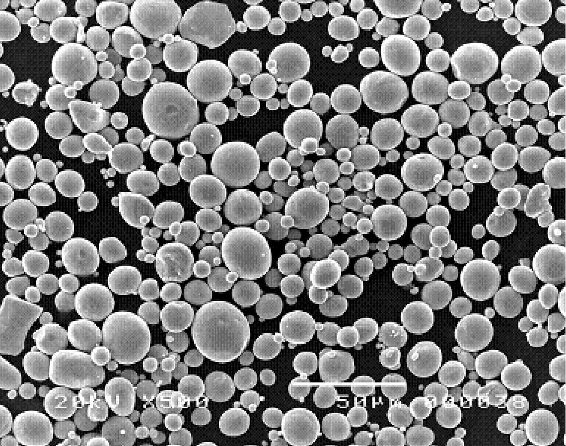
The gas-atomized titanium powder TILOP-45 (Osaka Titanium Technologies Co., Ltd.) was used in this study. The characteristics of the powder are listed in Table I. The morphology of the powder is shown in Figure 1. A unique polymer/wax-based low melting point binder, which is composed of the constituents with melting points of less than 130°C (266°F), was developed. The powder was mixed with the binder in a designed powder loading in a double-blade mixer at 130°C - 140°C (266°F - 284°F) for 3 hrs.
| Particle size (μm) | O (wt.%) | C (wt.%) | N (wt.%) | H (wt.%) | Fe (wt.%) | Theoretical density (g/cm³) | Powder morphology |
|---|---|---|---|---|---|---|---|
| <45 (1.77×10⁻³in) | 0.17 | 0.03 | 0.03 | 0.01 | 0.08 | 4.51 (282 lbm/ft³) | spherical |
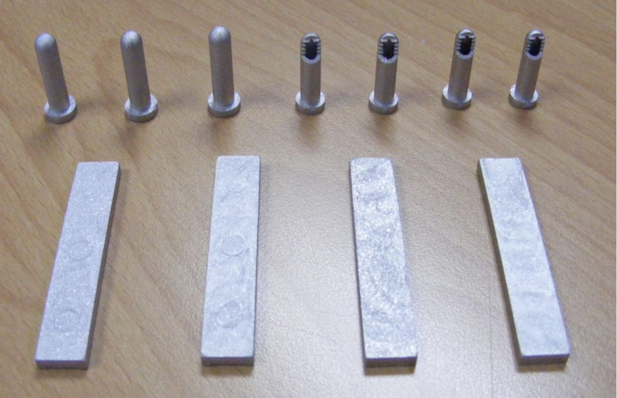
Specimens were fabricated in an injection molding machine at 140°C (284°F) with cooling water in the mould. Two-stage debinding process was adopted. The binder was removed first by solvent debinding in hexane for 10 hrs which opened the initial pore structure for subsequent debinding, and then by thermal debinding in a vacuum atmosphere of ≤ 10⁻³ Torr (1.934×10⁻⁵ lb/in²). The as-debound specimens were sintered in a high vacuum furnace with capability of 10⁻⁶ Torr (1.934×10⁻⁸ lb/in²) at 1200°C (2192°F) for 3hrs. Figure 2 shows the sintered specimens.
The carbon and oxygen contents were analyzed by a melt extraction technique with LECO System. The microstructure was observed by a scanning electronic microscope (SEM) JEOL JSM-5310 and a metallographic microscope Olympus-BX51M. Density was determined by using the buoyancy method. Hardness was measured by a hardness testing machine Mitutoyo MVK-H1 with the help of Vickers indenter. Dimension was measured by OGP Smartscope Flash. Flexural strength was measured by three-point bending test in universal testing machine MTS 810.
RESULTS AND DISCUSSION
The control of carbon and oxygen interstitial pick-up is a key to successful titanium PIM processes. The low melting point binder facilitated low temperature mixing at 130°C - 140°C (266°F - 284°F) and low temperature molding at 140°C (284°F) with cooling water in the mould so that the contamination of interstitials was effectively contained. Solvent debinding was carried out in the room temperature, and the remained binder was removed by subsequent vacuum thermal debinding. By comparing the carbon and oxygen contents of powder as received with those of the specimen after debinding, as shown in Table II, only 0.015wt% of carbon and 0.046wt% of oxygen were increased during the processes from mixing to thermal debinding, and the pick-up of carbon and oxygen was well controlled.
Two vacuum levels of sintering, i.e., 10⁻³ Torr (1.934×10⁻⁵ lb/in²) and 10⁻⁶ Torr (1.934×10⁻⁸lb/in²) respectively, were carried out as a comparison. The vacuum level of sintering affected the carbon and oxygen contents of the sintered specimens remarkably, as shown as in Table II. Compared to the carbon and oxygen contents of 0.28 wt% and 0.941 wt%, respectively, of the specimen sintered in the vacuum of 10⁻³ Torr (1.934×10⁻⁵ lb/in²), the carbon and oxygen contents of the specimen sintered in the vacuum of 10⁻⁶ Torr (1.934×10⁻⁸ lb/in²) were 0.052 wt% and 0.248 wt%, respectively, which satisfied the requirements of cp Ti grade 2, i.e., carbon ≤ 0.1 wt% and oxygen ≤ 0.25 wt%.
| Powder as received | Specimen after debinding | Specimen after sintering (10⁻³ Torr (1.934×10⁻⁵ lb/in²)) | Specimen after sintering (10⁻⁶ Torr (1.934×10⁻⁸lb/in²)) | |
|---|---|---|---|---|
| C (wt%) | 0.03 | 0.045 | 0.28 | 0.052 |
| O (wt%) | 0.17 | 0.216 | 0.941 | 0.248 |
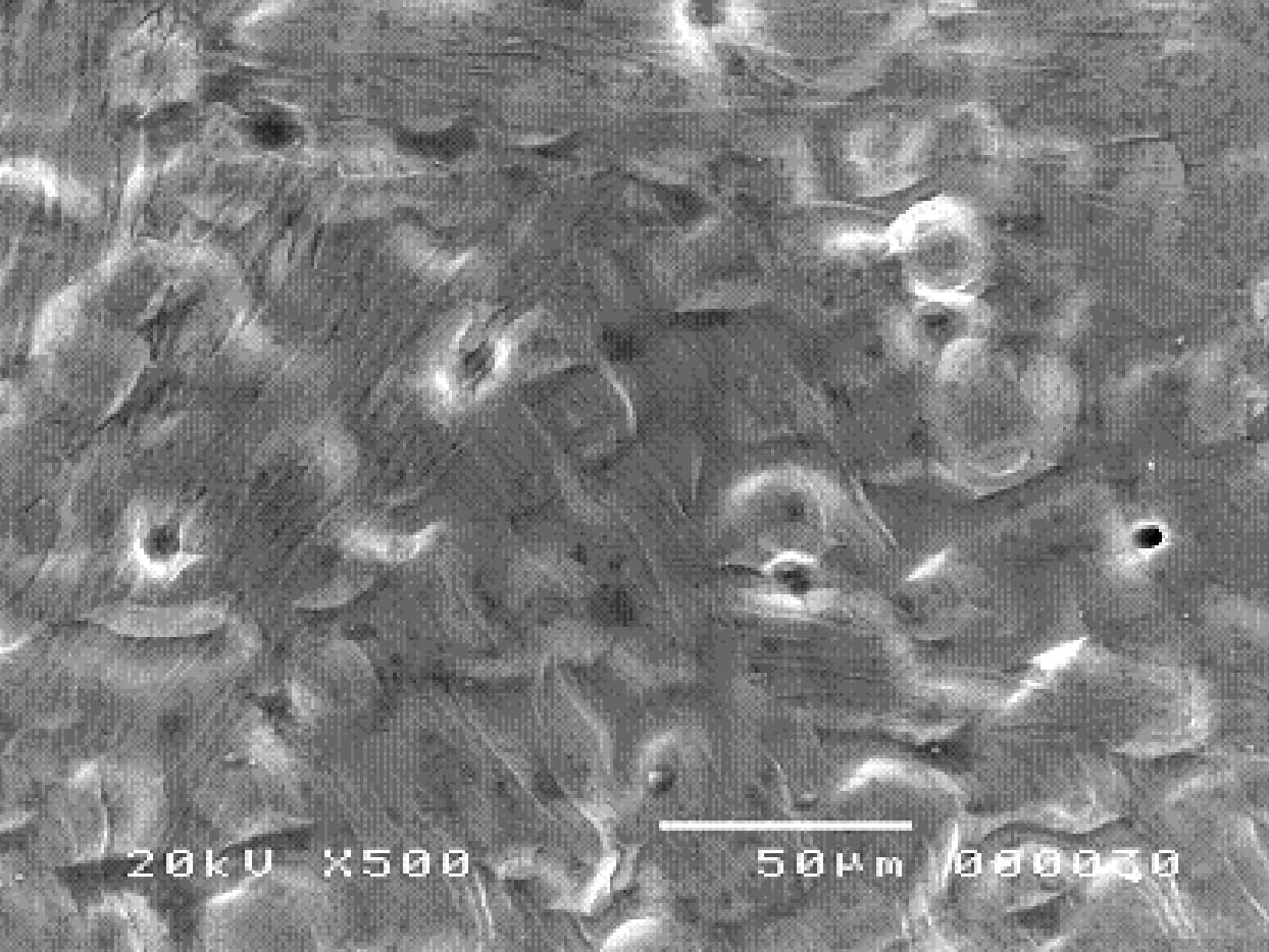
Figure 3 shows the SEM surface structure of the sintered Ti specimen, it is a soft roughness without the sharp edges as they appear during a metal-cutting process, and the surface roughness is about Ra1.5-2.0μm (5.91×10⁻⁵-7.87×10⁻⁵in). The surface is especially suitable for contact to bone tissue which is supposed to adhere to the implant, and stimulates cell proliferation and accelerates osseointegration. Thus, there is no need to treat the surface after machining as reported by Maeztu⁹ for the application of implants.
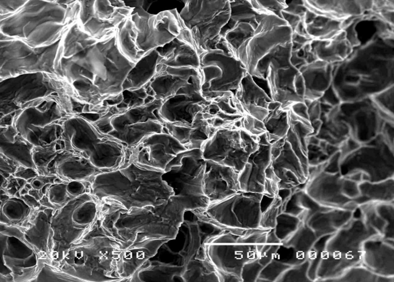
Figures 4 and 5 show the SEM photograph of fracture surface and the optical microstructure of the sintered Ti specimen respectively. The ductile fracture features, i.e., honeycomb structures, are found in Figure 4, and typical widmanstätten α structures are found in Figure 5.
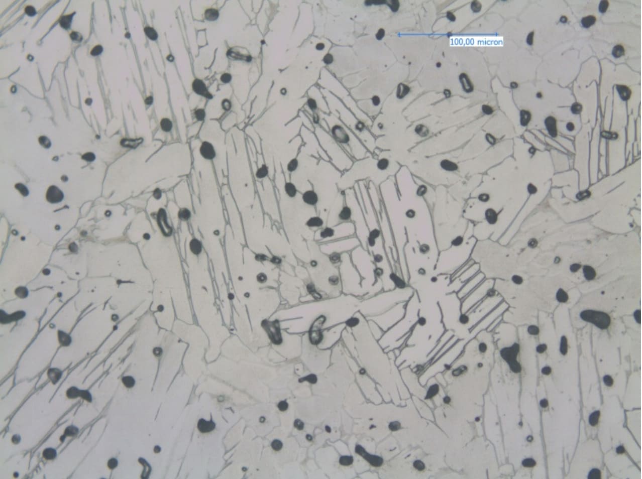
The Ti specimens were well sintered, and had homogenous microstructures. It was measured that the average porosity was 4.2%, density was 4.31 g/cm³ (269 lbm/ft³) and hardness was 204.5Hv, and the average values were the arithmetic means of 5 measured numbers respectively. The specimens were with good shape retention as shown in Figure 2, and have tight dimension deviation. For the sintered Ti test bar specimens, the detail measured length data are shown in Table III. The dimension deviation in length was within the range of ±0.04mm (1.6×10⁻³in) and about ±0.08%.
| Sample No | 1 | 2 | 3 | 4 | 5 | 6 | 7 | 8 | 9 | 10 |
|---|---|---|---|---|---|---|---|---|---|---|
| Length (mm) | 52.249 (2.057in) |
52.218 (2.056in) |
52.238 (2.057in) |
52.267 (2.058in) |
52.239 (2.057in) |
52.220 (2.056in) |
52.251 (2.057in) |
52.288 (2.059in) |
52.251 (2.057in) |
52.246 (2.057in) |
| Sample No | 11 | 12 | 13 | 14 | 15 | 16 | 17 | 18 | 19 | 20 |
| Length (mm) | 52.208 (2.055in) |
52.272 (2.058in) |
52.268 (2.058in) |
52.250 (2.057in) |
52.208 (2.055in) |
52.288 (2.059in) |
52.274 (2.058in) |
52.240 (2.057 in) |
52.241 (2.057 in) |
52.244 (2.057 in) |
| MEAN (mm) |
52.248 (2.057in) |
MAX | 52.288 (2.059in) |
MIN | 52.208 (2.055in) | SIGMA | 0.023 (9.06×10⁻⁴in) |
|||
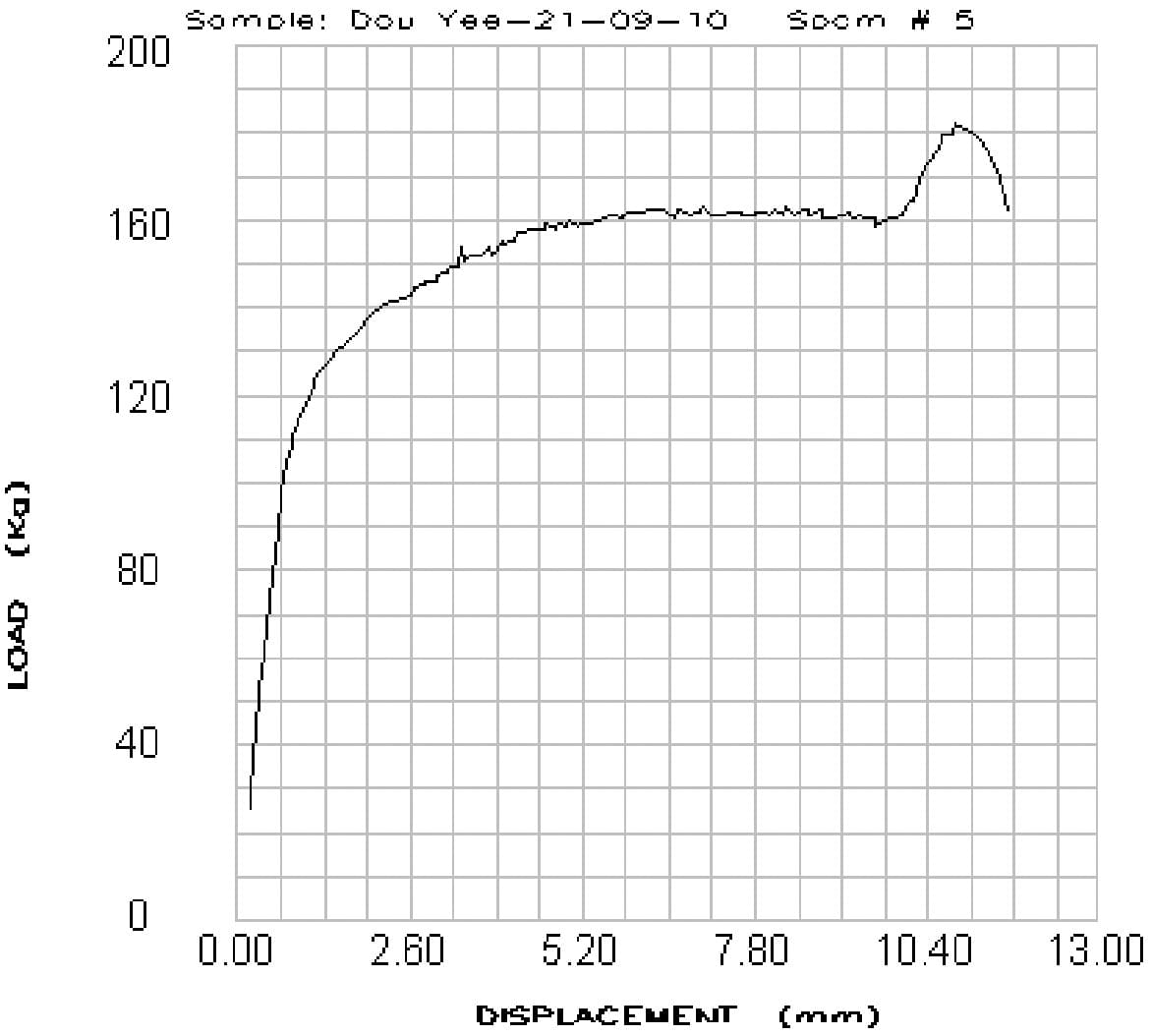
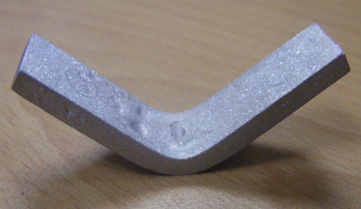
The average flexural strength of 1230MPa (1.78×10⁵psi), modulus of 85.4GPa (1.24×10⁷psi), and strain of 12% were measured by three-point bending tests, and the average values were the arithmetic means of 3 measured numbers respectively. Good ductility of sintered Ti specimens was achieved because of the low residual carbon and oxygen contents. Figure 6 shows the load vs displacement curve of three-point bending test of the sintered Ti test bar, and it demonstrates the features of a typical ductile material curve of load vs displacement. Figure 7 shows the bended Ti test bar specimen which was not broken after the peak load was passed during the three-point bending test.
CONCLUSION
A unique polymer/wax-based binder system was developed for the PIM of titanium. Low residual carbon content, 0.052 wt%, and oxygen content, 0.248%, of sintered Ti specimens were achieved by the unique binder system, feedstock preparation, low temperature injection molding, two-stage debinding and vacuum sintering processes. The density of 4.31 g/cm³ (269 lbm/ft³), fractional density 95.6%, and hardness of 204.5Hv of the sintered Ti specimens were measured. The sintered specimens were with good shape retention and tight dimension deviation.
REFERENCES
- R. M. German, "Titanium Powder Injection Moulding: A Review of the Current Status of Materials, Processing, Properties and Applications", Powder Injection Moulding International, 2009, vol. 3, no. 4, pp. 21-37.
- C. Ouchi, H. Lizumi and S. Mitao, "Effects of Ultra-high purification and Addition of Interstitial Elements on Properties of Pure Titanium and Titanium Alloy", Mater. Sci. Eng. A, 1998, vol. 243, no. 1-2, pp. 186-195.
- F. H. Froes and R. M. German, "Cost Reductions Prime Ti PIM for Growth", Metal Powder Report, 2000, vol. 55, no. 6, pp. 12-21.
- K. S. Weil, E. Nyberg and K. Simmons, "A New Binder for Powder Injection Molding Titanium and Other Reactive Metals", Journal of Materials Processing Technology, 2006, vol. 176, pp. 205-209.
- S. Guo, X. Qu, X. He, L. Zhou and B. Duan, "Powder Injection Molding of Ti-6Al-4V Alloy", Journal of Materials Processing Technology, 2006, vol. 173, pp. 310-314.
- T. Osada, H. Miura, Y. Itoh, M. Fujita and N. Arimoto, "Optimization of MIM Process for Ti-6Al-7Nb Alloy Powder", Journal of the Japan Society of Powder and Powder Metallurgy, 2008, vol. 55, pp. 726-731.
- H. Miura, T. Takemasu, Y. Kuwano, Y. Itoh and K. Sato, "Sintering Behavior and Mechanical Properties of Injection Molding Ti-6Al-4V Alloys", Journal of the Japan Society of Powder and Powder Metallurgy, 2006, vol. 53, pp 815-820.
- E. Ergul, H. O. Gulsoy and V. Gunay, "Effect of Sintering Parameters on Mechanical Properties of Injection Molded Ti-6Al-4V Alloys", Powder Metallurgy, 2009, vol. 52, pp. 65-71.
- M. A. De Maeztu, J. I. Alava and C. Gay-Escoda, "Ion Implantation: Surface Treatment for Improving the Bone Integration of Titanium and Ti6Al4V Dental Implants", Clin. Oral Implants Res., 2003, Vol. 14, No. 1, pp 57-62.